Why Old ThinkPads are Perfect!
I have been using ThinkPads for the past couple of years now, but the ThinkPad X220 seems to fulfill all my needs nevertheless. My first ThinkPad was the ThinkPad T420 but my problem with that was always its bulk and the battery life wasn't so good, that's most likely because of its Intel Core i7 though. As each year creeps around the corner, so do new laptop designs and they are slowly regressing. Sleeker and thinner seems to be the modern trend with every new generation of technology that arrives, but this has been greatly affecting user serviceability and not to mention the quality as well. Just compare the build quality of a traditional ThinkPad and a Macbook, the latter wouldn't even survive a fall, whereas the former is built to endure it. Nowadays, you actually have to open up a laptop to swap out the internal battery and RAM sticks are being soldered to the motherboards. Laptop users are beginning to lose their ability to even upgrade components anymore, they just have to buy new laptops.
Anyhow, sometime last summer I decided to switch to the ThinkPad X220 which is basically the equivalent to what I had before, except that it's much smaller (known to be ultraportable). I picked it up from Ebay for a little over US $100 - 8 GB of RAM, Intel i5, 240 GB SSD. Just in general, the X-series ThinkPads are really nice for everyday use and have excellent Linux support. I use it for everything and even though it came out in 2011, I don't really feel any drawbacks when using it either. It's also upgradeable and I use mine with an Ultrabase for convenience and this allows me to use a hard drive caddy as expandable storage. I feel like the ThinkPad X220 is at the sweet spot because it preserves the goodness of traditional ThinkPads (Classic ThinkPad keyboard, ThinkLight, etc.), but it still manages to utilize modern hardware. The ThinkPad X200 is also a great laptop, however, I find the Intel Core 2 Duo to be a draw back when using it so that's why I chose the ThinkPad X220. As we all know, the greatest disadvantage of using modern hardware is the fact that it is very contrained as to how you can modify it. ThinkPad X200s are compatible with Libreboot and by flashing that, you can completely remove the Intel ME, whereas on the X220 you cannot.
Coreboot, SeaBIOS, Intel ME (Intel Management Engine)
Not only does this laptop come with great hardware, but it is also compatible with coreboot. And if you haven't heard about coreboot, it is basically a free alternative to the proprietary BIOS that comes with most if not all laptops. Now, this isn't a 100% free software alternative like Libreboot, but it gets the job done. The main component of coreboot is free software, however, it still has to utilize the proprietary blobs from your non-free BIOS in order to operate properly. Another thing found within the non-free BIOS, is the Intel Management Engine. You can read up more about on Hackaday's writeup about it. It's essentially an extra CPU included with all Intel CPUs post 2011, and unfortunately you can't fully remove it, but you do have the ability to disable it and strip off a good chuck thanks to corna's me_cleaner. For Intel CPUs that came out after 2011, it is essential for Intel ME to be present in the BIOS chip, because you computer needs to be able to verify its signature in order to boot up. If you don't have Intel ME present, your laptop will consecutively turn off after every 30 minutes. It even has the ability to operate when the machine is powered off, not to mention it also has Direct Memory Access. I believe its original usage was for enterprise companies, however, this isn't something I need on my machine and would therefore like to disable this. In this guide I will show you how to do just that. Some people have even installed Windows 3.1 directly onto the BIOS chip.
More Information
I kept a series of notes that I made as I went through the process of flashing coreboot myself, and I found it to be quite helpful so I figured there could be some others who would also benefit from this. Ergo, I decided to write this guide as a way to help liberate more ThinkPads out there and people of course. My goal is to turn this process from what might seem like a painful one, to something a lot more approachable without too much frustration. After all, it is quite rewarding in the end and you come out with some new degree of knowledge.
Before you start with the process, you should be comfortable with using a Linux terminal and disassembling your laptop. There is always a possibility that you could brick your ThinkPad X220 when trying to flash coreboot. You are after all, connecting an external power supply to your BIOS chip, a lot of things could go wrong. It is highly unlikely if you follow the correct steps and take your time, but please keep it in mind. I take no responsibility if that were to happen so proceed at your own risk. Be sure to to back up your old BIOS in multiple places so that you can re-flash it if something were to go wrong.
You Will Need:
- Lenovo ThinkPad X220
- Raspberry Pi 3 B+ (Model B Plus)
- Pomona SOIC-8 5250 Test Clip
- Female to Female Jumper Wires
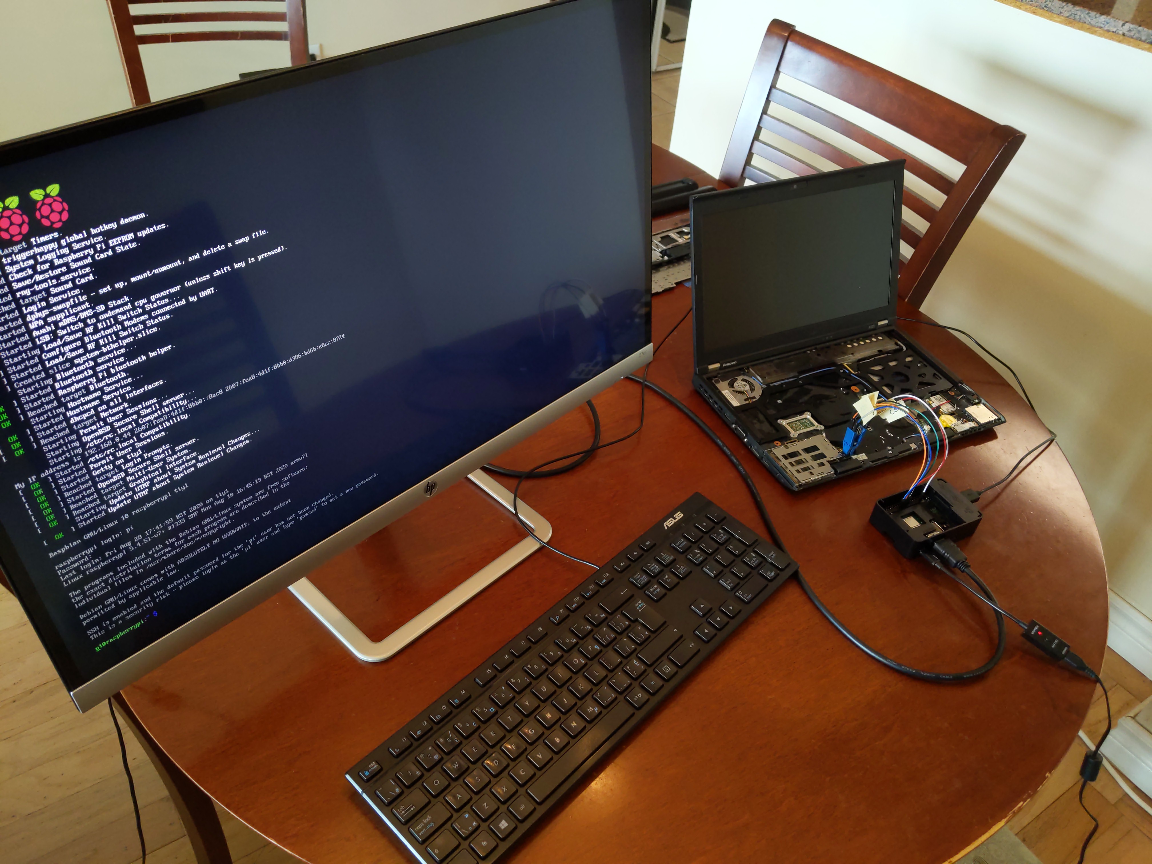
- An HDMI Monitor or you can SSH into the Raspberry Pi
- An HDMI cord and power supply for the monitor
- External keyboard if you choose to use an HDMI Monitor
- Secondary computer with Debian OS installed
Update the Embedded Controller on the X220
It is typically a good idea to update the Embedded Controller to the latest version before flashing coreboot. That is because coreboot cannot touch the Embedded Controller unless you revert back to the factory BIOS. To update it to the latest version, all you have to do is install the latest version of the factory BIOS. Be sure to get the official BIOS from Lenovo and this will update the Embedded Controller to the latest version.
Configure Raspberry Pi as a Flasher
First thing is first, we are going to setup the Raspberry Pi for SPI flashing. You are going to install the Raspbian OS and then you'll attach the Pomona 5250 clip with the female jumper wires. This is the part where you'd want to hook up your HDMI monitor and external keyboard to the Raspberry Pi, if that is what you're going to use. I believe there is a way out there to configure a headless Raspberry Pi (without monitor and keyboard).
Go to the Raspberry Pi's official site and download Raspberry Pi OS (32-bit) Lite.
After you've downloaded that, unzip it and copy that to the sd card with
dd, you'll be using this for your Raspberry Pi.$ sudo dd bs=4M if=2020-08-20-raspios-buster-armhf-lite.img of=/dev/< partition of sd card >Hook up an HDMI monitor and an external keyboard to the Raspberry Pi, then boot it up.
Run the following command on your Raspberry Pi and be sure to enable SPI Flashing and SSH for later use, when we go to copy over files from the Raspberry Pi. It is also a good idea to enable wifi as well, I find it to be the easiest way though raspi-config.
$ sudo raspi-configNext, we are going to check our network configuration to make sure it has properly been configured.
$ sudo nano /etc/wpa_supplicant/wpa_supplicant.conf

ctrl_interface=DIR=/var/run/wpa_supplicant GROUP=netdev
update_config=1
country=< Insert 2 letter ISO 3166-1 country code here >

network={
 ssid="< Name of your wireless LAN >"
 psk="< Password for your wireless LAN >"
}
By now, SPI flashing should already be enabled if you did it through raspi-config. In case it isn't, check in
/boot/config.txtfor the following line:$ sudo nano /boot/config.txt dtparam=spi=onOnce that is all setup, go ahead and reboot.
$ sudo rebootNow you are going to install the required software for flashrom and hardware flashing.
$ sudo apt-get update && sudo apt-get dist-upgrade && sudo reboot
$ sudo apt-get update && sudo apt-get install libftdi1 libftdi-dev libusb-dev libpci-dev subversion
$ sudo apt-get install build-essential pciutils usbutils libpci-dev libusb-dev libftdi1 libftdi-dev \
zlib1g-dev subversion
$ sudo apt-get install flashrom
Finally we need to add the SPI kernel modules to
/etc/modules, so that they persist after reboots.$ sudo nano /etc/modules spi_bcm2835 spidevAnd run the following:
$ sudo modprobe spi_bcm2835
$ sudo modprobe spidev
Shutdown the Raspberry Pi.
$ sudo poweroff
ThinkPad X220 Disassembly
Before you start to disassemble the ThinkPad X220, power it off and remove the battery and AC power! Then hold the power button down for 60 seconds (without the battery of course) to discharge the capacitors on the motherboard. Do not leave the battery plugged in at all costs!
Next, remove the keyboard and palmrest, you can follow Lenovo's guide for more information on how to do that. Basically, there are 7 screws on the back that you want to remove, these are holding the keyboard and palmrest in place. I previously thought that you had to remove all screws on the back, but it turns out to be only those 7. I've indicated which ones on the diagram down below.
Here is the diagram of the locations of the screws:
    Bottom of the ThinkPad -- 'X' marks screws to be removed
   +-----------------------------------------------------------+
   |   xxxxxxxxxxxx Battery xxxxxxxxxxxxxxxxxxxxxxxxx          |
   |   xxxxxxxxxxxxx Area xxxxxxxxxxxxxxxxxxxxxxxxxxx          |
   |                                                           |
   |                                                           |
   |                                                           |
   |              +----X----------------+                      |
   |              |                     |                      |
   |              |      Memory         |                      |
   |              |       Door          |                      |
   |   X          |        X            |             X        |
   |      X       +---------------------+                      |
   |                  X               X                        |
   +-----------------------------------------------------------+
After you took out the screws, flip over the ThinkPad and push the keyboard forward. This will allow you to grip the keyboard near the palmrest and just pull up from there.
The keyboard will still be attached to the motherboard via a ribbon cable, so remove that by pulling up on it.
Lastly, flip the palmrest up and this time click the ribbon cable (it is sort of like a clip). The palmrest should be free and now you can remove it.
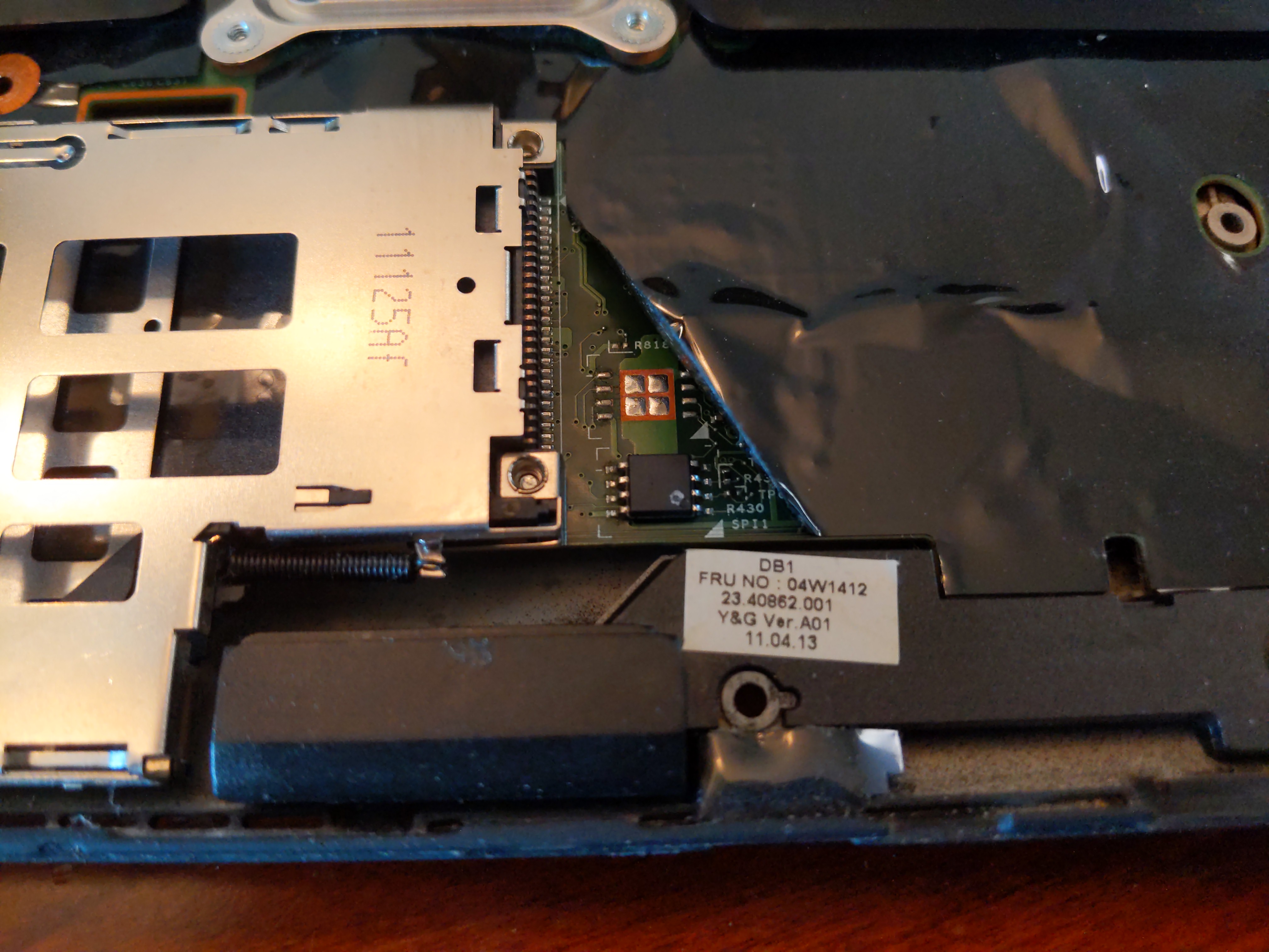
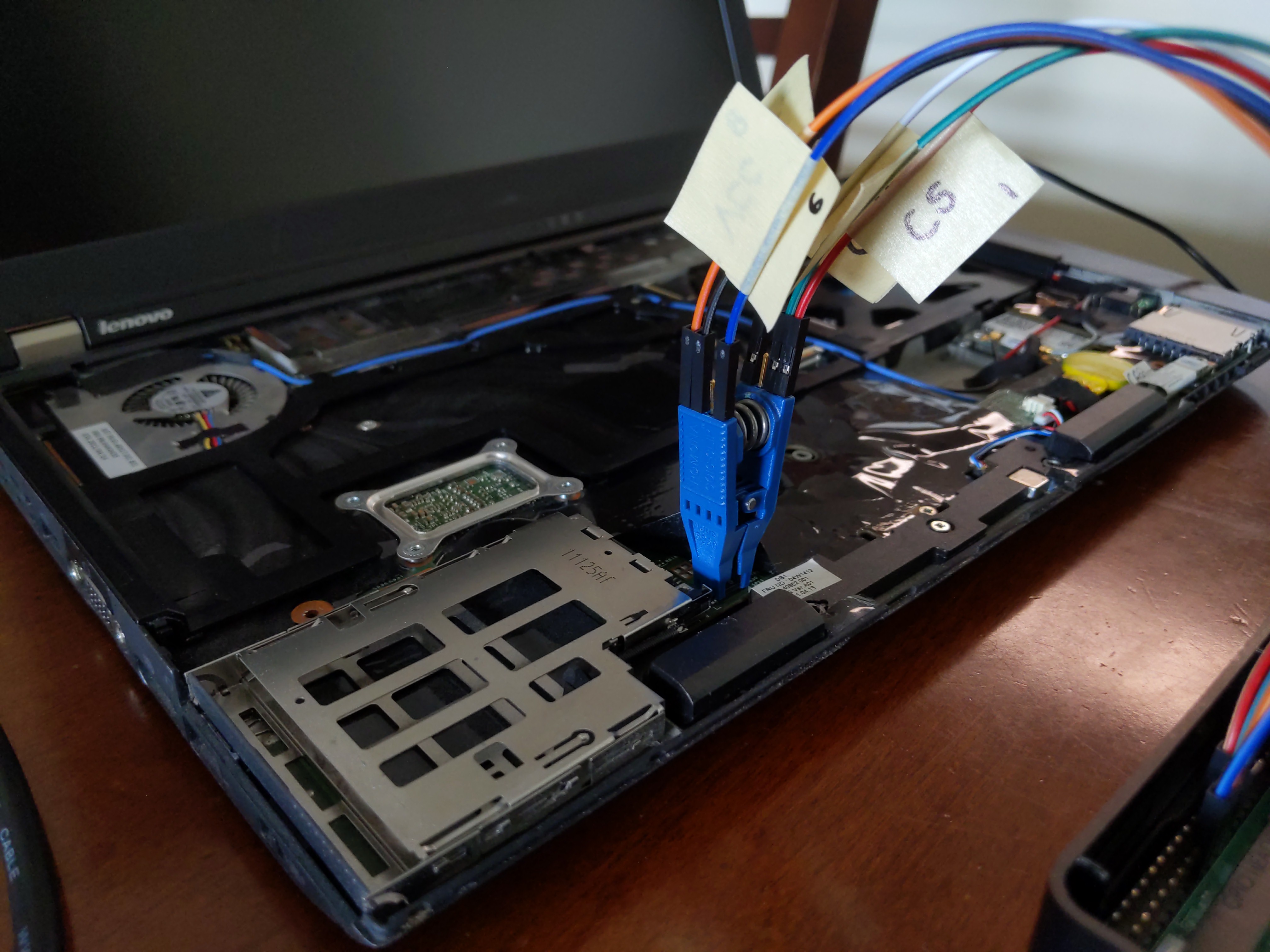
Once you've removed the keyboard and palmrest, you should have something that looks like the image down below. Right there, is the BIOS chip in the bottom-left corner of the motherboard. This BIOS chip is a SOIC-8 chip and there is only one of these on this motherboard. Some ThinkPads will have a SOIC-16 chip and others will have more than one BIOS chip on the motherboard itself.
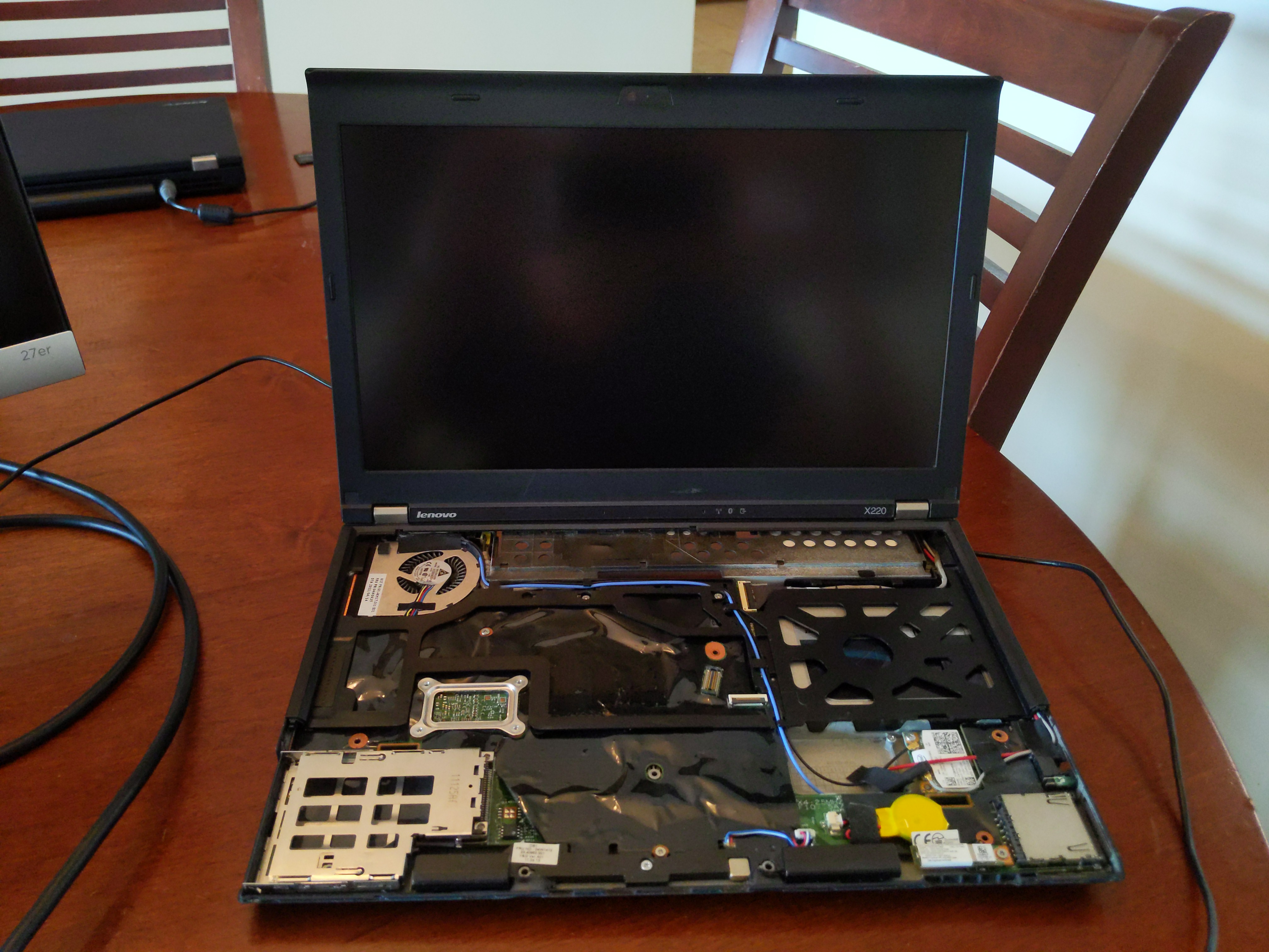
The BIOS chip should be just right of the ExpressCard slot, under the black antistatic film. It'll most likely always be covered if you or someone else hasn't already tried flashing the BIOS chip before. So don't be startled if you can't see it right away, all you have to do is lift up the bottom left of the film and that should reveal the flash chip. It is quite small, so connecting the Pomona clip is usually always the hardest part. That's why it's important to get a good quality clip before attempting this step.
Reading the Flash Chip by Using Flashrom
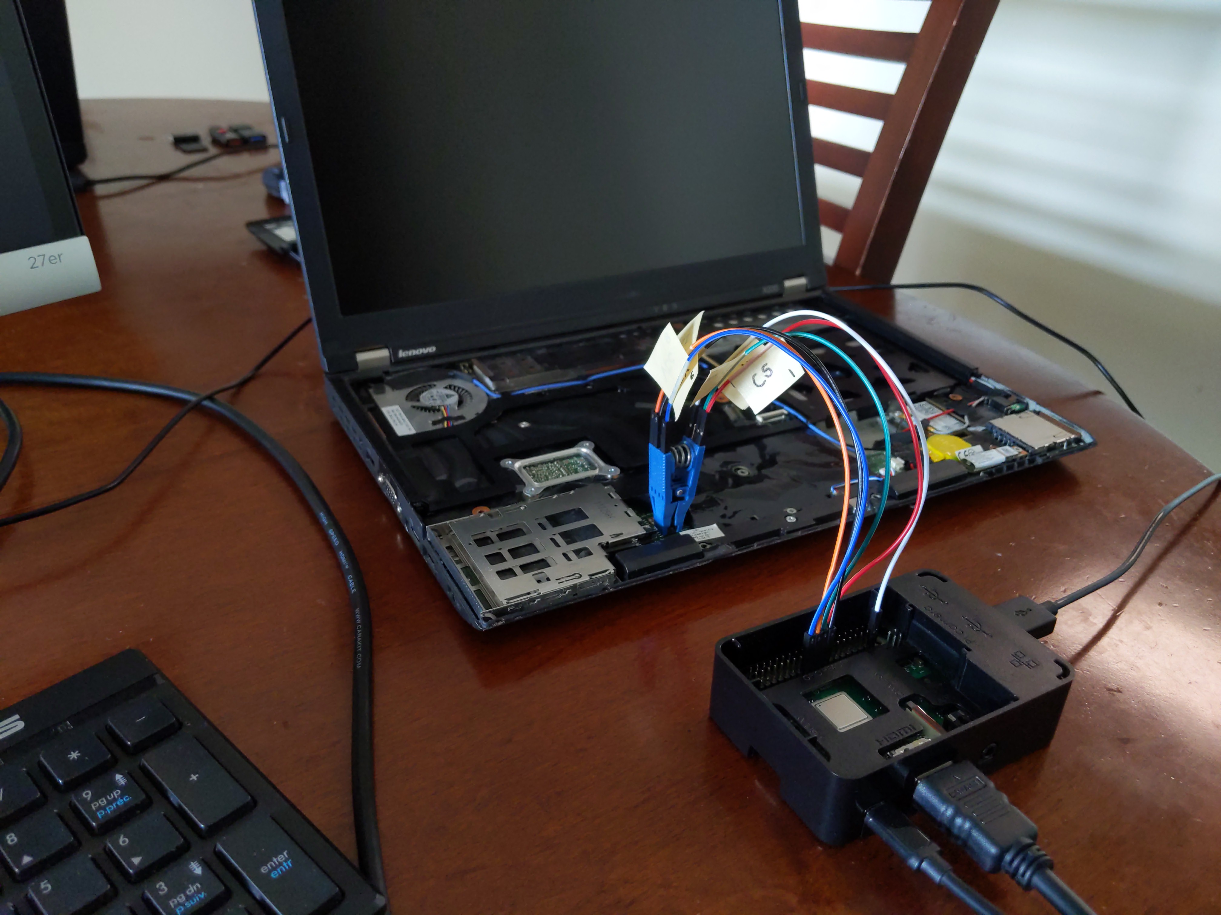
At long last, you can hook up the Pomona clip to your Raspberry Pi and then connect it to the BIOS chip on your motherboard.
Here is the ThinkPad X220 BIOS chip pinout, which should be identical to your Pomona clip (N/C stands for no charge):
 Screen (furthest from you)
             __
  MOSI  5 --|  |-- 4  GND
   CLK  6 --|  |-- 3  N/C
   N/C  7 --|  |-- 2  MISO
   VCC  8 --|__|-- 1  CS

   Edge (closest to you)
Here is the pinout on the Raspberry Pi 3+ (Model B Plus), keep in mind that it has 40 pins rather than 26:
   Edge of pi (furthest from you)
 L                                                             CS
 E                                                             |
 F +--------------------------------------------------------------------------------------------------------+
 T |    x    x    x    x    x    x    x    x    x    x    x    x    x    x    x    x    x    x    x    x    |
   |    x    x    x    x    x    x    x    x    x    x    x    x    x    x    x    x    x    x    x    x    |
 E +--------------------------------------------^----^----^----^---------------------------------------^----+
 D                                              |    |    |    |                                       |
 G                                             3.3V  MOSI MISO |                                      GND
 E                                           (VCC)            CLK
   Body of Pi (closest to you)
Note: VCC is 3.3 volts (they're the same thing). When you go to wire everything up, I found it quite helpful to label the wires using a sharpie and some masking tape. That way I was able to match the jumper wires between the Pomona clip and Raspberry Pi without too much hassle. If this part isn't done correctly, then the next steps will not work.
Read the contents of the BIOS chip with
flashrom. First you are going to see if you can even detect the chipset(s). If you getNo EEPROM/flash device found, then double check your connections from the previous step. This happened to me once, and all I had to do was re-attach the Pomona clip.pi@raspberrypi:~ $ sudo flashrom -p linux_spi:dev=/dev/spidev0.0,spispeed=128 flashrom on Linux 5.4.51-v7+ (armv7l) flashrom is free software, get the source code at https://flashrom.org Using clock_gettime for delay loops (clk_id: 1, resolution: 1ns). Found Macronix flash chip "MX25L6405" (8192 kB, SPI) on linux_spi. Found Macronix flash chip "MX25L6405D" (8192 kB, SPI) on linux_spi. Found Macronix flash chip "MX25L6406E/MX25L6408E" (8192 kB, SPI) on linux_spi. Found Macronix flash chip "MX25L6436E/MX25L6445E/MX25L6465E/MX25L6473E" (8192 kB, SPI) on linux_spi. Multiple flash chip definitions match the detected chip(s): "MX25L6405", "MX25L6405D", "MX25L6406E/MX25L6408E", "MX25L6436E/MX25L6445E/MX25L6465E/MX25L6473E" Please specify which chip definition to use with the -c < chipname > option.For most of you, you will have a Winbond flash chip "W25Q64.V" and so you'll need to set the -c parameter to that. In my case, I happen to have a Macronix chip and so I need to specify which one I want to use. I ended up using the first one, MX25L6405. All the chips ended up having the same sha512sum outputs in the end, so it doesn't matter anyway.
After
flashromdetects the chip(s), you are going to read it and verify that the sha512sums match. By usingsha512sum, you can verify that you have a good read on the flash chip. If they don't match, then go back and repeat the previous steps, and check your connections between the Pomona clip and the Raspberry Pi. The quality of your Pomona clip can also affect your reads on the flash chip, so keep that in mind as well.pi@raspberrypi:~ $ sudo flashrom -p linux_spi:dev=/dev/spidev0.0,spispeed=128 -c MX25L6405 -r factory1.rom pi@raspberrypi:~ $ sudo flashrom -p linux_spi:dev=/dev/spidev0.0,spispeed=128 -c MX25L6405 -r factory2.rom pi@raspberrypi:~ $ sudo flashrom -p linux_spi:dev=/dev/spidev0.0,spispeed=128 -c MX25L6405D -r factory3.rom pi@raspberrypi:~ $ sha512sum factory*.romEach read could take anywhere between 30-45 min each, so don't be worried if it is taking a while. This is because of the spispeed, which you've set to 128 and this'll ensure that you'll get a good read on the flash chip. I've decided to use
sha512sumovermd5sumbecause of its more accurate algorithm for check hash codes. The former is a lot more robust than the latter.You can continue with the process on your Raspberry Pi, or you can move one of the BIOS dumps onto another computer and continue from there. I personally used
scpto transfer thefactory1.romfile over to my Debian laptop. Compiling coreboot on the Raspberry Pi is an excruciating process because of how slow it is, I believe that it would take around 10 hours for it to compile thecoreboot.rom. On my Debian laptop, it took around 30 minutes, so just something to consider. If you are going to use a Debian computer, then run:user@debian:~$ scp pi@192.168.0.XX:factory1.rom .Download the latest version of me_cleaner to neuter the Intel Management Engine on the
factory1.romdump. I used the-Soption to enable the HAP AltMeDisable kill-switch and remove the extra code to shrink the file. You can't completely remove the Intel ME, but thankfully we have the option to neuter it, which basically disables the software from running after startup.$ cp factory1.rom cleaned.rom $ sudo apt-get install python3 $ git clone https://github.com/corna/me_cleaner ~/me_cleaner $ ~/me_cleaner/me_cleaner.py -S cleaned.romAfter neutering the Intel ME, download the latest version of coreboot onto wherever you will be compiling it. Thereafter, you will compile and use
ifdtoolto extract the proprietary blobs fromfactory1.rom, and this will be used for compiling thecoreboot.romlater on. You will also move the proprietary blobs into the right directory too, that'll be in the3rdparty/blobs.$ git clone https://review.coreboot.org/coreboot ~/coreboot $ cd ~/coreboot $ git submodule update --init --checkout $ cd ~/coreboot/util/ifdtool $ make $ sudo make install $ cd ~ $ ifdtool -x ~/cleaned.rom $ mkdir -p ~/coreboot/3rdparty/blobs/mainboard/lenovo/x220 $ cd ~/coreboot/3rdparty/blobs/mainboard/lenovo/x220 $ mv ~/flashregion_0_flashdescriptor.bin descriptor.bin $ mv ~/flashregion_2_intel_me.bin me.bin $ mv ~/flashregion_3_gbe.bin gbe.bin
VGA BIOS Extraction
This part is not necessary if you are going to use something other than VGA BIOS, however, I highly recommend you do this. There are pre-extracted VGA BIOS images out there, but I find that they don't work too well and can actually cause problems when in use. My first time compiling coreboot, I used one of those pre-extracted VGA BIOS images and then my display would every once in a while black out or freeze in the middle of me using it. As soon as I followed this process and extracted my own VGA BIOS image from cleaned.rom, I had no problems. It isn't too hard either, I mean if you have already gotten this far into the guide, then you can for sure complete the following.
Download the UEFITool and compile it on your computer. You will also need to install the C++ compiler and the Qt5 library to make it work.
$ sudo apt-get install qt5-default build-essential
$ git clone https://github.com/LongSoft/UEFITool
$ cd UEFITool
$ qmake uefitool.pro && make
$ ./UEFITool
Whenever you want to run UEFITool, just
cdinto the~/UEFITooldirectory and run./UEFITool.Once you got that running, click on "File" and open the
cleaned.romfirmware image, that should open the contents of that file.After you've opened the firmware image, click on "File" again and then on "Search". Navigate to the tab where it says "Text" and search for "VGA Compatible BIOS", make sure that "Unicode" is checked off.
Now the program should have found a match and double click on the bottom section that is highlighted blue. Then another file in the middle section of the screen will also become highlighted blue, that is what you want.
Right click on the file that is highlighted in the middle section of the screen and select "extract body". Then save it as "
vgabios.bin" in~/coreboot/3rdparty/blobs/mainboard/lenovo/x220.If you would like to, you can verify that you have extracted the right binary blob by installing
fcode-utils(Debian). Runromheaders vgabios.binand look for "0x030000 (VGA Display controller)" next to "Class code".The last step is not necessary but it's always a good idea to verify, that way in case sometimes does go wrong later on, you'll know that it isn't your VGA BIOS dump. It's always better to be safe than sorry, if you verify and take your time throughout this process, that'll minimize your chances of making mistakes.
Building and Compiling Coreboot
If you have succeeded up until now with everything, you are well on your way to freedom (sort of). This part of the process is usually the most fun (depending on who you are). I will be using a bootsplash image, however, that is not necessary if you don't want to include it. I personally compiled this on my Debian laptop, as I have previously mentioned. Now would be a good time to transfer over the ~/coreboot directory if you haven't already done so and would like to. You can compile it on the Raspberry Pi, but just know it'll take a really long time (between 8-12 hours).
First install the required packages needed to compile the coreboot rom. There is an explanation for each of the packages on the coreboot wiki. These dependencies are required by
make nconfigto work properly.For a Debian-based system:
$ sudo apt-get install git build-essential gnat flex bison libncurses5-dev wget zlib1g-devFor an Arch-based system:
$ sudo pacman -S base-devel gcc-ada flex bison ncurses wget zlib gitThe configuration down below is what I've used in the past and it tends to be a very stable setup. Be careful to not accidentally select the wrong settings. Simply go through each category and select the settings that I've listed down below, and do not deselect any of the default settings either.
$ cd ~/coreboot
$ make nconfig

General
  -*- Use CMOS for configuration values
  [*] Compress ramstage with LZMA
  [*] Include coreboot .config file into the ROM image
  [*] Allow use of binary-only repository
  [*] Add a bootsplash image
      (< PATH TO BOOTSPLASH IMAGE >) Bootsplash path and filename

Mainboard
  Mainboard vendor (Lenovo) --->
  Mainboard model (ThinkPad X220) --->
  ROM chip size (8192 KB (8 MB)) --->
  (0x100000) Size of CBFS filesystem in ROM

Chipset
  [*] Enable VMX for virtualization
  [*] Set IA32_FEATURE_CONTROL lock bit
      Include CPU microcode in CBFS (Generate from tree) --->
  [*] Use native raminit
  [*] Ignore vendor programmed fuses that limit max. DRAM frequency
  [*] Add Intel descriptor.bin file
      (3rdparty/blobs/mainboard/$(MAINBOARDDIR)/descriptor.bin) Path and filename
  [*] Add Intel ME/TXE firmware
      (3rdparty/blobs/mainboard/$(MAINBOARDDIR)/me.bin) Path to management engine firmware
  [*] Add gigabit ethernet firmware
      (3rdparty/blobs/mainboard/$(MAINBOARDDIR)/gbe.bin) Path to gigabit ethernet

Devices
      Graphics initialization (Run VGA Option ROMs) --->
  [*] Use onboard VGA as primary video device
  [*] Re-run VGA Option ROMs on S3 resume
      Option ROM execution type (Native mode) --->
  -*- Enable PCIe Common Clock
  -*- Enable PCIe ASPM
  [*] Enable PCIe Clock Power Management
  [*] Enable PCIe ASPM L1 SubState
  [*] Add a VGA BIOS image
      (< PATH TO VGA BIOS IMAGE >) VGA BIOS path and filename
      (8086,0126) VGA device PCI IDs
  [*] Add a Video Bios Table (VBT) binary to CBFS
      (src/mainboard/$(MAINBOARDDIR)/data.vbt) VBT binary path and filename

Generic Drivers
  [*] Support Intel PCI-e WiFi adapters
  [*] PS/2 keyboard init

Console
  [*] Squelch AP CPUs from early console
  [*] Show POST codes on the debug console

System Tables
  [*] Generate SMBIOS tables

Payload
      Add a payload (SeaBIOS) --->
      SeaBIOS version (master) --->
      (3000) PS/2 keyboard controller initialization timeout (milliseconds)
  [*] Hardware init during option ROM execution
      Payload compression algorithm (Use LZMA compression for payloads) --->
  [*] Use LZMA compression for secondary payloads
      Secondary Payloads --->
  [*] Load coreinfo as a secondary payload
  [*] Load Memtest86+ as a secondary payloada
  [*] Load nvramcui as a secondary payload
  [*] Load tint as a secondary payload
      Memtest86+ version (Stable) --->
After you've finished, hit
F6and thenEnterto save and finally pressF9to exit.Now that you've configured the settings for your coreboot rom, it is time to compile it.
$ make crossgcc-i386 CPUS=4
$ make iasl
$ make
The new coreboot rom will be placed inside of
~/coreboot/build/coreboot.rom. If your Raspberry Pi happens to have run out of memory, then go ahead and create a swapfile to continue the process or restart the compilation.If you used a laptop as I did for the compiling, you'd then want to transfer over the
coreboot.romfile, so that you can flash it onto your chip. If you used a Raspberry Pi, then you can ignore this step.user@debian:~$ scp /home/user/coreboot/build/coreboot.rom pi@192.168.0.XX:
Flashing Coreboot
The final part is flashing the
coreboot.romonto the flash chip. But before you go ahead and do that, you have to make sure you still have a good read on the chip, otherwise it might not write onto it correctly. At this point, you should know whether you have a Winbond chip or a Macronix chip like me, modify these bottom commands accordingly to your chip type. Lastly usesha512sumto verify the hash codes on the reads.pi@raspberrypi:~ $ sudo flashrom -p linux_spi:dev=/dev/spidev0.0,spispeed=128 -c MX25L6405 -r factory1.rom pi@raspberrypi:~ $ sudo flashrom -p linux_spi:dev=/dev/spidev0.0,spispeed=128 -c MX25L6405 -r factory2.rom pi@raspberrypi:~ $ sha512sum factory*.romIf the sha512sums match, then you can proceed onto the last and final step of flashing coreboot!
pi@raspberrypi:~ $ sudo flashrom -p linux_spi:dev=/dev/spidev0.0,spispeed=128 -c MX25L6405 -w coreboot.romWhen you run this command, if you see "Erasing and writing flash chip... FAILED", don't worry this is perfectly normal. It will just use some other erase function and then it should say "Verifying flash... VERIFIED." That is when it has finally finished flashing.
Make sure that you shutdown the Raspberry Pi before disconnecting the Pomona clip. Then make sure there is no power source connected to the Raspberry Pi and after you can disconnect the clip.
pi@raspberrypi:~ $ sudo poweroffOnce you've disconnected the Pomona clip from the motherboard and powered up the ThinkPad X220, you should see the bootsplash image that you used from up above (if you decided to use one). You should also see SeaBios briefly for about 3 seconds after the bootsplash went away. And if it boots into your hard drive, then you have been successful! If that did not happen, then you can try re-flashing coreboot and even try repeating this entire guide if you must. You can always re-flash the original BIOS by using the command below if you get stuck.
pi@raspberrypi:~ $ sudo flashrom -p linux_spi:dev=/dev/spidev0.0,spispeed=128 -c MX25L6405 -w factory1.rom
Other Useful Information
- Tyler Cipriani's Guide – This guide uses the Winbond chip so refer to this if you have the same one.
- Karl Cordes' Guide – Very useful guide and it uses the Macronix chip like the one I have.
- NRoach44's Guide – Great information on extracting the VGA BIOS, this was a huge help.
- Tianocore Guide – This guide is for using Tianocore instead of SeaBios, visit it for more information.
- Techentalks's Guide – I know this is for the Thinkpad T420 but it is still very useful.
- Coreboot Wiki – The official documentation on building coreboot.
- tripcode!Q/7's Video – I found this to be quite useful for the VGA BIOS extraction as well.
- Mike Bob's Video – You can watch more on how to configure the coreboot rom with actual footage of the flashing process.